Thursday 29 September 2011

Improving waterwheel control

While Nick Jones was helping us to mill our first flour last week, he observed that we could do with a bit more power from the wheel, as well as the ability to control wheel speed from inside the mill. This control might be done by the dump valve, a board we can drop out of the bottom of the launder. We also noted that the dump valve was not effective as an emergency stop when the water flow was high - enough water just 'toboggans' over the dropped flap to keep the wheel turning.

So today we set about improving the action of the dump valve. The options were either to make a second board drop, doubling the width of the gap, or to link a vertical board to the dump valve mechanism so that it forms a block across the launder just below the dump valve. Dropping a second board would be a major engineering project, so we concentrated on the second option. The main difficulty was that the available lifting motion from the dump valve mechanism at the point where the new board needs to fit was only about 9cm, and we would need nearer 20cm.

After exploring many ideas, we concluded that the only way to generate the extra movement is to use a second lever linked to the dump valve actuator with its own separate pivot. We cobbled together an experimental rig using a hoe handle with its pivot in the weatherboard wall of the wheel shed to check the theory and it worked, as the pictures show. Parts of the permanent mechanism will be made over the next few weeks.

We also noted several issues that may affect the efficiency and power of the waterwheel. Firstly, it leaks badly, and stopping water escaping from the buckets would increase power. Secondly water splashes out of the first bucket due to the height from which it falls from the launder. The side cheeks we noted at New Abbey might help, however we also noted that the end of the launder is not parallel to the axis of the wheel. Finally, as the wheel is pitchback, the water falling from the launder is moving in the opposite direction to the wheel and therefore its horizontal momentum will act as a brake. We began to design a box for the end of the launder to reverse the direction of the final fall of water.

Tuesday 20 September 2011

Flour!!!

At last, after 4 years of work, we finally milled!

This was the first time since at least 1940 the mill has produced flour
.
We make the final adjustments...


We arrived early to make sure all was well, and made a few minor changes and adjustments. Nick Jones, from Little Salkeld watermill, arrived with two sacks each containing 25kg of grain. After a few further checks, he took us through the process of starting up for the first time. A lot to learn, from how to untie the paper sacks easily rather than fighting them, to balancing wheel speed and grain flow rate to get a good product.

...before Nick Jones arrives
to fill the grain hopper


In the event the product was proclaimed to be good and the whole thing worked smoothly, surprisingly so for a first run. We had a small celebration and carried on milling for a couple of hours. Nick reckoned the system could be run faster to increase output, but that isn't really a problem for us, we don't want tons of the stuff!

The short video shows some of the bits of the process in action, with nice mechanical sounds.

Monday 19 September 2011

Visit to New Abbey Mill, Dumfries


The New Abbey waterwheel


The stone floor

This year's Acorn Bank staff and volunteer outing took us to New Abbey Mill (also to Threave garden, a very interesting and pleasant place, but a garden blogger will have to write about that).

New Abbey Mill is a single wheeled watermill with 3 pairs of stones. Unfortunately, it is unable to work at present due to bearing problems with one of the stones. We were, therefore, only able to see it in action on the excellent 12 minute video. The guide was well informed and humorous - as a result Chris Braithwaite said that we ought to be funnier!

Among useful and interesting things we saw at New Abbey were: control of the wheel speed from the milling area by means of a diverter (our "dump valve"); the complete drying kiln; the Heath-Robinson sack hoist; the side cheeks under the launder to prevent water spilling sideways out of the wheel.

Thanks to Sara for organising the trip and providing us with tea and cakes at Threave.

A pretty, and wet, flower
at Threave

Tuesday 13 September 2011

Good progress!


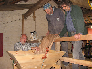
Ray and Richard examine the
finished flour chute
The flour chute is finished at last! Ray finally made the front covers, one of which is hinged for access to clean the inside. It will also allow the fall of flour to be seen - one of the issues with preparing the mill for milling is that all the interesting mechanical bits get covered up. We then sanded and cleaned the whole thing, sealed the inside joints with food grade silicon sealant, and applied some wood stain to the outside to prevent it looking too "new".


Richard carried on with making the parts for the damsel. This picture shows the top and bottom plates which will mount on the damsel shaft and carry the 4 bars making the eccentric to agitate the shoe.


The greenhouse window winder

Oak in the wrong place
After lunch we scrounged some nice mechanical bits from the window opening system in the old greenhouse, which has been demolished to make way for a fancy new one. The screw drive looks as if it would make a fine remote actuator for the gate valve, so the miller can control the water flow, and hence wheel speed, from within the mill.


Progress was held up a bit by the large oak branch that the gales had blown down on the path to the house.

Tuesday 6 September 2011

More fun with 3-dimensional geometry!


The flour chute, showing the rectangular side pieces
and tricky 3-D triangular spaces
Today Ray and Bob continued to work on the flour chute. Ray brought the final output tube which he had built at home, and we mounted that on its brackets. It then remained to build the side pieces to bridge the gap between that and the upper part that is built into the hurst frame. Unfortunately, the sides would have to be cut with angles in 3 dimensions, and even then it began to look as though they might have to be bent! After several cardboard templates and much head-scratching we went for coffee.

The coffee seems to have done the trick, as we then worked out that we could fit rectangular pieces to the sloping part of the chute, and make simpler triangular pieces to join them to the upper and lower parts.

The saw and the failed triangles


Ray's compound mitre saw managed to cut the first three triangular pieces, which have one edge at an angle other than 90 degrees to the flat surface as well as a 38 degree point angle. However, the fourth seemed to require a combination of angles and directions that the saw didn't want to accomodate. Finally, after many unsuccessful attempts, we made a jig to hold the wood at 45 degrees to the saw bed and finally glued the last piece in place.

All we need now is the front cover